Illustration, in History and in the Future
We’ve been watching many episodes of Pete Beard’s YouTube channel on the unsung heroes of illustration. Beard does a nice job of giving you the life details of these people, along with showing you representative samples of their work.
For a period that lasted roughly 150 years, a talented illustrator could become rich and famous. The increasing general literacy rates and growth of leisure time created an expanding market for books in the late 18th century. There were also technological breakthroughs in printing, which made adding illustrations to books more affordable, and publishers found that the illustrated books sold better. And while the concept of periodical magazines goes back to the 17th century, it was in the later part of the 19th century that illustrated magazines exploded in popularity.
Magazines were the YouTube or Twitter of their day, the place where culture was discussed and developed, and where art movements gained their momentum. They commissioned illustrations for their covers and their content, and once an illustrator had a reputation, they could make a good living. Once an artist was well known, they became sought for advertising and poster work. Some did merch, too.
It’s fascinating to see the enormous quantity and quality of work. As someone who has dabbled in art, it’s a little overwhelming. You can view a lot of the work online. Beard’s channel is a good introduction, but then you can go down the rabbit hole and look at scans of Jugend magazine, the outstanding Illustration History site from the Norman Rockwell Museum, commercial sites like Granger, and so on. More than you can possibly absorb is just a web search away.
The growth of photography and techniques for photographic printing changed the equation in the 1950s. Illustration took a back seat, with many localized renaissances like 60s music posters and 80s ‘zine culture.
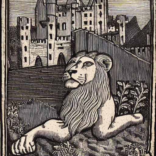
Today, another revolution is happening. Over the past year, “Artificial Intelligence” art has gone from being a fairly obscure discipline to the point where it is producing stunning results. I’ve been playing with Stable Diffusion, and the results are both impressive, unsettling, and fascinating. This system works on a mathematical model that was fed a huge volume of images and text from the internet. Given a text prompt or general directing image, it uses that model to creates a set of mathematically weighted values representing how it “understands” your request. It then uses random noise and repeated filters to create an image that satisfies those mathematical weights.
The creation of the initial model is extremely computationally expensive and involved. The creation of images using that model, however, is something that can be done on any reasonably modern home computer.


There’s debate about “who creates the art,” when using a system like this. After all, it only “knows” the art it was fed in the initial model creation. So, in that sense, it can’t create anything “new” — and yet, the way it combines things is at a low enough level that there isn’t any reproduction of any of the original work. That being said, it’s still biased by the work it was trained on. It “understands” beauty and ugliness based on the descriptions of the images it was created with. This bakes in a lot of other subtle prejudices: ranging from abstract ideas like what constitutes futuristic, to more fraught ideas like what traits define racial terms. It’s telling that the initial release of the software put a “not safe for work” filter in place, because such a high percentage of the images of women in the initial model were nude.
People are already using this software to generate printed images and even movies. There’s definitely an art to creating the source prompts to get the results you want, but this is getting easier and easier. I think it will be a matter of weeks or months before the clip-art business is just a front-end to this kind of software. It will be fascinating to see where this ends up.