Setting up a WyzeCam3 as a Stand-alone Unit with Thingino
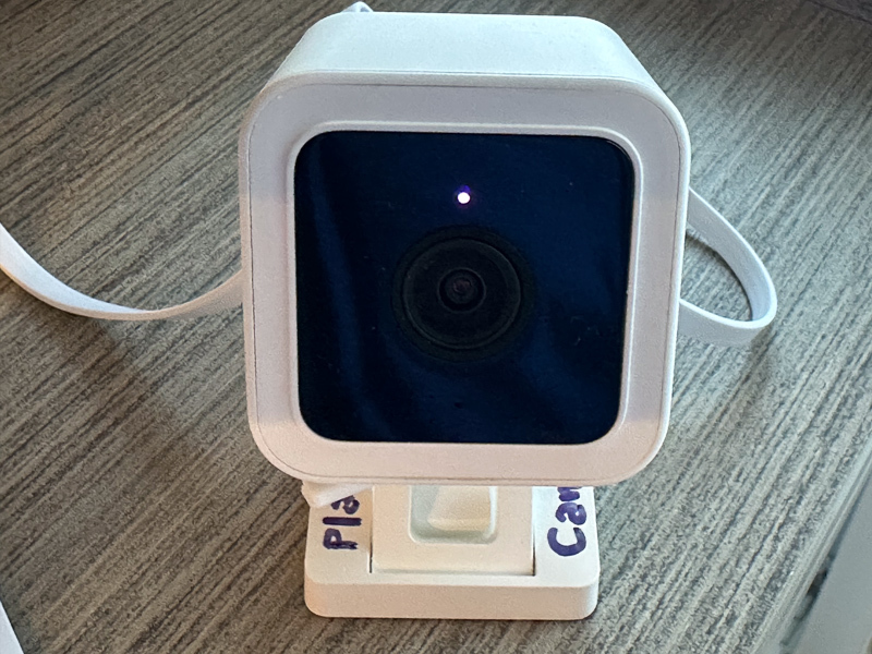
The WyzeCam3 is a relatively cheap device that can capture video. It can be set up for motion capture or continuous recording. But even if you install a memory card in the device, it will want to use the company’s app and stream data via their cloud storage. I don’t know much about how much thought went into their codebase with regard to security, but this is the kind of device where the usual answer is “not much.”
Furthermore, the WyzeCam requires an app for installation and configuration, and the WyzeCam3 needs to connect to your 2.4GHz WiFi network. Oops. I have no 2.4GHz WiFi network. It’s all 5Ghz here. Now what?
Enter Thingino, an open-source replacement firmware. One nice feature is that it allows the camera hardware to enable an Wi-Fi access point (“AP mode”) — it creates its own 2.4GHz WiFi network, which my Mac will happily connect to! Once the camera is set up, I can further customize things, and have it write motion capture files to the SD memory card rather than someone’s cloud.
So, there’re a few gotchas that were not obvious to me:
- When you’ve downloaded the firmware, you need to use something to flash it as an image on your micro-SD (e.g., Balena Etcher, Rufus, or the like). I came across at least one guide that said “simply copy the files onto the SD card” which is incorrect!
- When the Thingino installation has completed, you connect to the WiFi network it creates. A captive portal form pops up for basic configuration. You’re asked to provide a device name, a root password, and a WiFi SSID and password. There’s also a checkbox to have the camera create its own WiFi hot-spot (the aforementioned AP mode). If you’re going to have it work in AP mode, the SSID and password you provided above are used for the network it creates. If you are not, it will use those to connect to an existing network. Don’t make the mistake of giving the SSID and credentials for your existing network and then checking that checkbox!
- Once you’ve installed Thingino via the SD card and you’ve connected to the network admin, you might want to set up motion capture to “Storage.” You’re gonna have to reformat that SD card first! The UI won’t complain, or tell you why it’s not working, but it just won’t let you submit the form. Thingino recommends formatting in exFAT.
- Even if you’ve configured the “Motion” panel, you have to click on the Storage link and tell it that you really mean the storage mounted at /mnt/mmcblk0p1 (or the mountpoint for your SD card ). You can have motion sensing and capture enabled, but it will fail if you haven’t taken that step.
- You may need to go into storage manager to tell it how to clear off space before you can enable motion capture. The control panel for motion capture does not seem consistent.
- Even after all that, the motion capture details may not save correctly. At least the firmware version I downloaded, it just wouldn’t save the settings consistently. There is a workaround! You have to ssh in to the camera, and set the values:
Enable motion detectionjct /etc/prudynt.json set motion.enabled truejct /etc/prudynt.json set motion.send2storage true
Configure the storage destinationjct /etc/send2.json set storage.mount /mnt/mmcblk0p1jct /etc/send2.json set storage.send_video true
Set motion sensitivity, range is 1-8, default is 1. Higher = more sensitivejct /etc/prudynt.json set motion.sensitivity 5
Configure clip length (in seconds)jct /etc/prudynt.json set motion.video_length 15
Restart prudynt/etc/init.d/S31prudynt restart - If you want to restore the original WyzeCam firmware, the instructions say to copy the original config files that get backed up by the Thingino install into the root directory of the SD card, name the file autoupgrade-full.bin, and then power it up. Oh, did you have that SD card formatted in exFAT? Ha ha, the firmware replacement process requires the SD card to be formatted FAT32 with Master Boot Record (MBR). The failure mode for this is somewhat opaque — it does seem to do something, and then in my case it announced it was ready for setup… in Italian. It was not ready for setup, though, as it hadn’t replaced the firmware.
Other Problems:
- There’s no way to have the device do its own time management without a network (NTP). You can set the clock (ssh in, use the “date” command in BusyBox) but it doesn’t survive power-cycles.
- I set up an isolated 2.4GHz guest network for the cameras that only allows DNS and NTP traffic to/from the internet. Then I went to reconfigure the cameras to use that network. From the admin panel, when I changed the network settings and turned off the “create AP,” it never seemed to connect. I had to reflash to the original firmware and then reinstall Thingino.
Other notes:
- If you set up the Thingino camera with an AP network, it defaults to the IP address 100.64.1.1