Projector Stand, v.1.0. Status: failure.
We have a ViewSonic short-throw projector hooked up to an old Mac Mini and a DVD player, which we use to watch videos and YouTube. We project the shows on the living room wall, or sometimes, to be easier on our backs, upward to create “ceiling cinema.”
After taking a class on OnShape given at Crash Space, I thought an adjustable projector stand would be a good project to really teach me the software.
I’ve used a half dozen modeling / CAD programs over the past few years, and each one has a different learning curve. I should probably write up what I like and dislike about all of them. For now, I’ll just say that OnShape is a JavaScript modeler that runs in your browser1, and is developed by the team behind SolidWorks. It has all manner of professional design capabilities, materials planning, and so on — far, far more than I’m capable of using at this point.
My design was based on the plan to use the Crash Space laser cutter and 5mm birch plywood to build the final stand. It would be adjustable on one axis to swing from wall to ceiling modes, would have a simple locking mechanism, and would be stable enough to old the projector steady.
After far longer than I thought was reasonable, I had a design done in OnShape. For joining the edges with nice interleaving tabs, I used the Laser Joint add-in. The rest was based on measuring the physical objects and thinking about what I wanted. One nice thing in OnShape is that you can set motion constraints and simulate solids. This way, I could paste in a stand-in for my projector, and see that the range of motion would be correct.


Now that I had a design, I needed to export the individual pieces to be laser cut. There are layout add-ins available for OnShape, but none seemed to work for my design (probably because I didn’t take the time to thoroughly read the manual). Instead, I selected the primary face of each piece, and exported it as a DXF drawing.
Initially, I had problems. Nothing recognized the DXF files, even Inkscape, which generally is very good with this sort of thing. Aha! My version of Inskscape was out of date. Upgrading solved the problem. From Inkscape, I could export valid dimensioned PDFs.
From here, I had one other problem. One piece, the base, was larger than the 24″ x 12″ bed of the laser cutter. So I had to figure out a way to design two pieces that would fit together nicely. Taking inspiration from skull or pelvis suture patterns and the more happy shape of butterfly wings, I came up with a design. I imported the PDFs into Affinity Design, and split the base into two similar pieces. Since I already created some nice vector butterfly outlines, I figured I’d embellish the structure as well (I can’t help myself).
I ended up with four PDFs of actual-size designs that I could use on the laser cutter. I later realized that they are not the most efficient designs in terms of minimizing cuts, but I hadn’t been thinking of that when laying them out.
Here are the PDFs:


So those got cut out, and then brought home.


I clamped and glued the base, and misaligned it by a bit, but with some judicious sanding was able to make the relatively subtle mistake into something screamingly obvious. Oh well.

Then, I clamped and glued the sides to the base, and the hinge pieces to the platform piece. After the glue had dried, I sealed the pieces with polyurethane which turns out to be harder to brush on evenly than I expected. I ended up having to sand it away in places so that some of the closer tolerances would still fit.
From there, it was a simple matter to assemble. I added a spring to pull the locking bar up, and mounted the projector.


Hooray, it worked… sort of. There were a few problems that made themselves known right away. The first was dimensional.
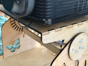
In the original design, I measured the size of the projector — which I’d had to do very carefully so the three mounting screws would line up correctly. But what I didn’t take into consideration is that in use, the projector has cables plugged in, and they take up space. As per the photo below, I hadn’t accounted for about an inch and a half of needed clearance. This prevents positioning vertically for a good ceiling tee-vee experience.

Another problem, however, is the one that will require a new design. I anticipated that the combination of the large disc-in-hole hinges and the overall friction would result in fairly low force on the locking teeth against the locking bar. This proved to be true, but also the high friction in the system made it hard to tell when the locking bar was entirely clear when doing position adjustments. This, in turn, made it unfortunately easy to break the teeth.

So there it is. Version 1.0 earned a grade of “Failure.”
Version 1.1 is under consideration. Possible approaches are a pin-and-hole locking mechanism (slower and more difficult to change), or possibly forgoing locking altogether and using a screw-down friction-based brake instead. After all, the projector only weights a few pounds. A switch of materials would also work, but I’m kind of set on wood. I like the look of wood far more than I do the look of the various acrylics that I’d be able to cut with the Epilog. I suppose I could use a service to cut out of metal, but quarter-inch metal would be pretty heavy for the purpose.
1 The fact that you can write this kind of serious software, and that it runs in a web browser on a five-year-old notebook computer is really astonishing to me. Yet, it is indeed true.
Leave a Reply