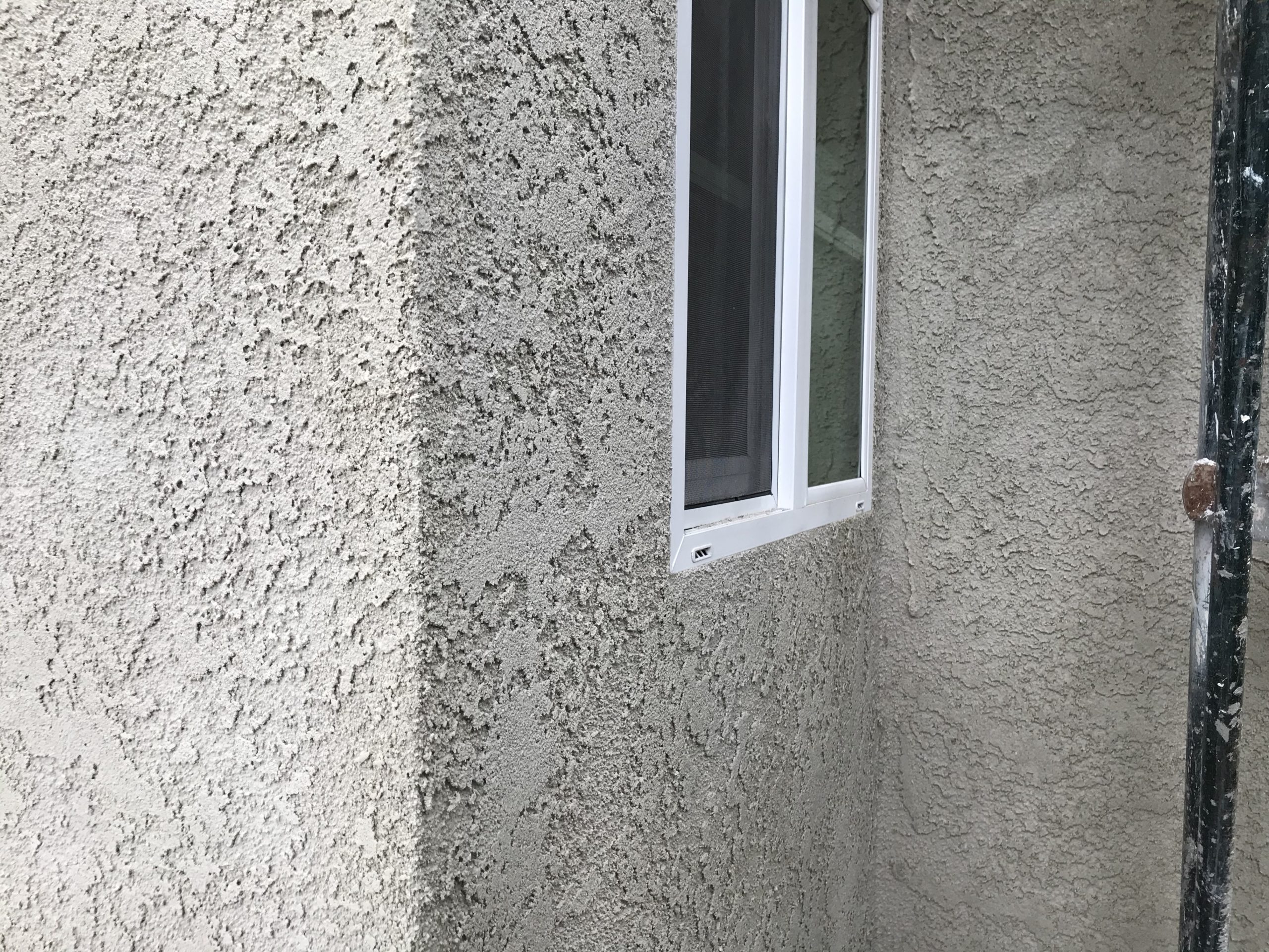
Tax-day Update
Final stuccoing took place today, and the painting of the inside continues.
https://www.fogbound.net/archives/2021/04/15/tax-day-update/#respond
Final stuccoing took place today, and the painting of the inside continues.


It’s been a while since there’s been an update here.
The crew has been painting and tiling inside the unit. The upstairs bathroom is approaching completion.
Meanwhile, we’ve been doing further revisions of the front yard. I had to move some slate from under the concrete bench, which would have been impossible without judicious application of leverage and use of a jack. We added an archway over the bench for roses and morning glory to grow onto, and moved the mad bird feeding rig more than a squirrel’s leap from the new arch.


The crew was working on Saturday too, so today’s the first time I’ve got an updated view of the stucco.
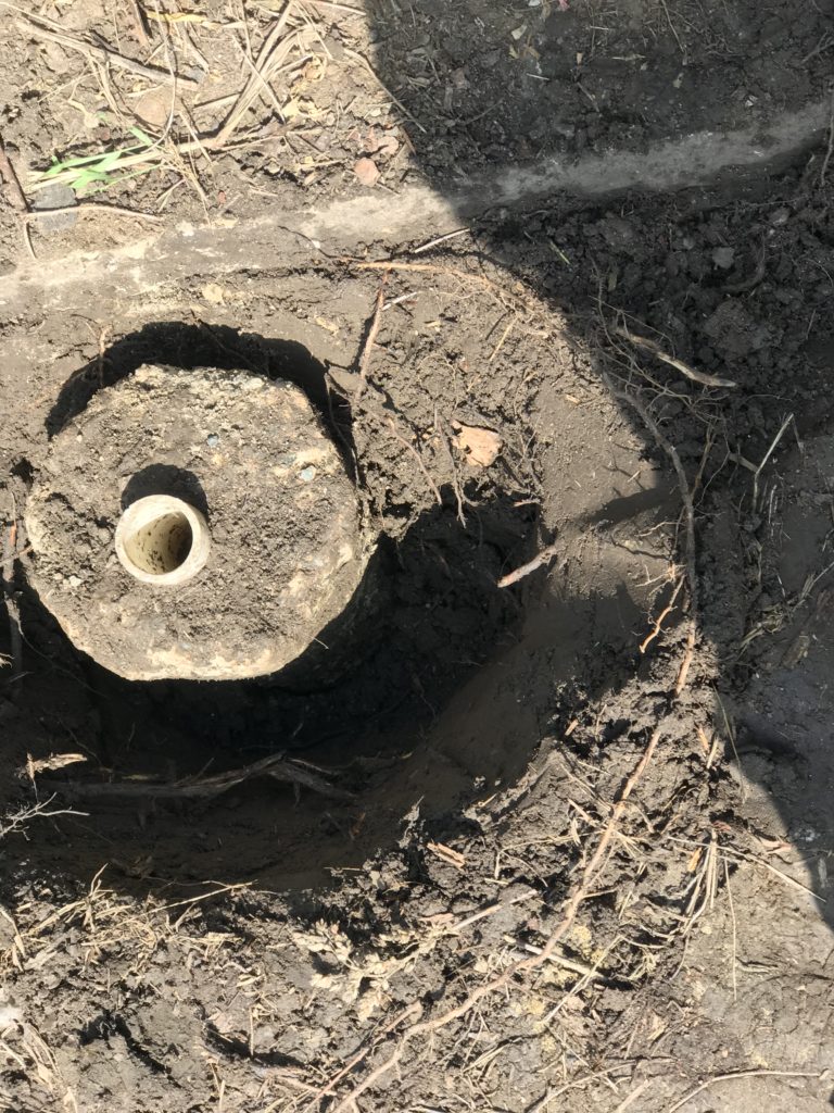
Meanwhile, the sprinklers up front were not working correctly. I’m no Hercule Poirot, but I was able to get to the cause of the problem. And fix it.


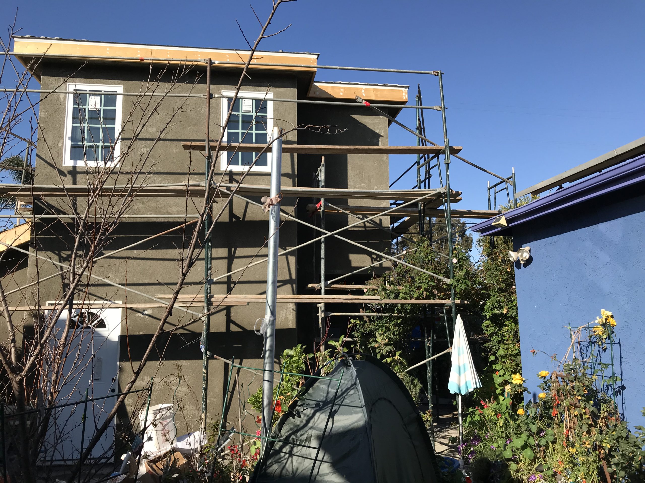


This morning started with a lot of heavy machinery to bring the stucco and sand, and to deliver the mixer and start it all going. The stucco is being applied by hand. Perhaps the surface will be sprayed on? It remains to be seen.


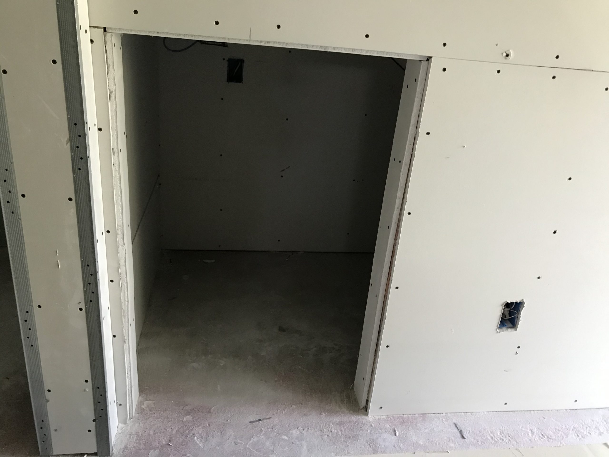
Over the weekend, I looked around the unit and saw the progress on the drywall and the shower. These pictures don’t really seem all that different, but a lot of detail work is being done in corners and edges. And, of course, the shower pan hadn’t been there before!
There was a drywall inspection, where they evidently audit the size and number of screws used to secure it.